How to defeat LED Ghosting on WPC Era Pins
There are now LEDs available that can reduce or eliminate ghosting & flicker.
They accomplish this by adding a bridge rectifier & capacitor into the base of the lamp.
They cost more than LEDs without the base circuitry and there is not as wide a selection but they can be a good alternative.
Following are the two sources of anti-ghosting / flicker LEDs that I currently know of:
Ablaze Ghost Busters
http://www.pinballlife.com/
Noflix Pinball LEDs
http://www.pinballcenter.eu/
Updates May 29, 2011
-Updated the analysis of the lamp matrix current spike.
-More details on different lamp matrix driver versions.
What is Ghosting?
When talking about pinball machines and LED's, the term 'ghosting' is frequently used to describe the behavior of an LED that should be off glowing dimly when another LED is turned on.
What causes ghosting?
Anything that can cause an LED or incandescent lamp to briefly receive current when it should not can cause ghosting. The effect is much more pronounced with LED's because of their quick turn on time relative to incandescent lamps.
The predominant cause for Williams/Bally WPC Era pins is a mixture of a lamp matrix software driver timing issue and what appears to be an issue with the WPC ASIC.
What is a 'WPC Era' Pinball Machine?
Here's a link with a list of games: Williams_Pinball_Controller
How can LED ghosting be eliminated?
In the 1995 timeframe, the Williams software designers modified the lamp matrix device driver code to work around the WPC ASIC issue and to modify the timing with how matrix is controlled. For 'most' cases this appears to have eliminated the ghosting issue. I say most because I have read a number of posts where people say they still have LED ghosting issues even when they are running ROM's with the updated driver code. I have also read posts stating that the ghosting issue is more prevalent when Rotten Dog power/driver boards are used.
I have written a program which will do the following:
- Take a WPC Game ROM as input and analyze it to determine if it contains the old or updated lamp matrix driver code.
- If the ROM has the old code, the program will update/patch the driver with the new code.
- The program prompts the user to enter a new game version.
- The ROM game version is updated and the checksum is re-calculated.
Any WPC pin produced from 1996 onward will have the updated driver code.
Williams designers also updated the driver code for a number of popular games produced before 1996. Some examples of earlier games with updated ROMs are:
- AFM rev 1.13
- WH2O rev LH-6
- TZ rev 9.4H
Here's a great video from The Korn demonstrating the differences between a ghosting & non-ghosting LED in a BoP.
Fixing WPC LED ghosting via software patching from The Korn on Vimeo.
Analysis of the issue
Following is a simplified drawing of a 3x3 lamp matrix. (The actual WPC matrix is 8x8)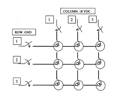
There are 3 columns and 3 rows. Each column and each row has a switch. If both the column's and the row's switch is closed then then the electrical circuit completes and the lamp lights.
For example, closing the column 2 switch and the row 3 switch will light the bottom lamp in the middle column.
For the WPC lamp matrix the switches are actually transistors. Columns are driven by TIP107 transistors and rows are driven by TIP102 transistors.
The WPC lamp matrix driver runs once approximately every 2mS. Every time it runs it increments the column which is turned on. ie: column 1 is on for 2 mS then column 2 is on for 2 mS then column 3, 4, 5, 6, 7, 8, and back to column one.
So the total cycle time for all 8 columns is 16mS. When a column is turned on anywhere from zero to all 8 lamp rows may be lit.
Following are oscilloscope waveforms from my testing.
Scope Setup (WPC Fliptronics-2: CFTBL)
----------------------------------
Channel 1 (Yellow): Column-4 logic: U18-19
Channel 2 (Blue): Column-5 logic: U18-12
Channel 3 (Purple): Row-1 logic: U13-8
Channel 4 (Green): Column 4 current probe: J137-4
I'm testing with cointaker 'superbright' LED's
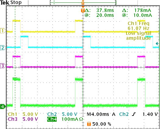
This capture shows two full 16mS cycles with Column 4 Row 1's lamp being lit.
Column 4 is driving approximately 180mA of current. During my testing no other rows are being lit so cointakers superbright led's draw an average of (180mA / 8) = 22.5mA when used in the lamp matrix.
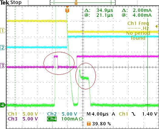
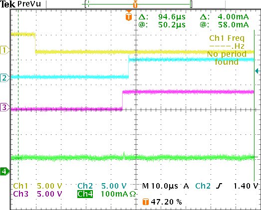
This capture shows the problem.
Here Column 5 & Row 1 is being turned on.
Note: The current spikes (Green) that occur on column 4. This is what causes Column 4 Row 1's LED to ghost when Column 5 Row 1's LED is turned on.
The first spike is massive. It peaks at over 2 Amps.
The 2nd current spike is about 180mA.
So what is happening?
Following is the driver code:
CLR WPC_LAMP_ROW #Turn all the Rows off
STAA WPC_LAMP_COLUMN #Increment from Column 4 to Column 5
STAB WPC_LAMP_ROW #Turn rows on that should be on for Column 5
The second (180mA) current spike that occurs for column 4 is the problem that has been analyzed in the past. The driver is turning column 5 on at the same time it is turning column 4 off and then immediately turning the row on.
Column 4's transistor takes a little while (in this example about 6uS) to actually turn off. So, when row 1 is turned on, column 4's transistor is still conducting allowing column 4 / row 1's LED to light.
From the CPU board's schematic, you can see that WPC chip pin 60 is the 'LAMP ROW' latch signal and pin 47 is the DREN signal. The WPC chip generates these signals by decoding the 6809 CPU bus address and clocking signals to determine when the CPU is writing to the 'LAMP ROW' control register.
The first (left) current spike is due to to how the 68B09E handles the CLR instruction.
The large column 4 current draw indicates that all 8 rows are being turned on. (ie: 0xFF is being latched into the row register)
From the HD68B09E data sheet:
Execution sequence of CLR instruction.
Cycle-by-cycle flow of CLR instruction (Direct, Extended,
Indexed Addressing Mode) is shown below. In this sequence
the content of the memory location specified by the operand
is read before writing "00" into it.
<See data sheet for the rest>
What happens is the WPC ASIC does not distinguish between a read and write bus cycle when decoding
the WPC_LAMP_ROW access enable signal which is sent to the power driver board.
When the CLR instruction executes the read cycle, the D0..D7 data bus signals to the power driver board
are 0xFF. This causes the power driver card to latch all 8 lamp rows ON.
On the following write bus cycle all 8 rows are turned off.
So the CLR instruction READ access intermittently turns all 8 row lamps on.
The following bus WRITE cycle then turns them all off.
Here you can see the glitch during the CLR instruction occurs even when no lamps (rows) are being turned on.
Here's a complete listing of the Lamp matrix driver code from the CFTBL L-4 ROM.
How did Williams fix the issue
So how did the designers fix the issue?Basically, they eliminate use of the CLR instruction and write zeros to the row & column data earlier in the code to turn off the rows and column transistors. Also, when re-enabling the matrix they switch from writing the column first to writing the row first.
Pseudo code:
CLRB
STAB WPC_LAMP_COLUMN
STAB WPC_LAMP_ROW
perform calculations for about 30uS
STAB WPC_LAMP_ROW
STAA WPC_LAMP_COLUMN
Here's a complete listing of Updated Lamp Matrix Driver code from the MB 1.06 ROM.
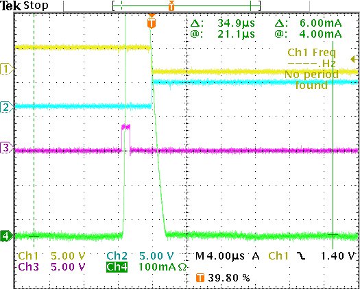
Here's a trace of the updated driver. Note how column 4 turns off about 37uS before column 5 turns on. Note how there are no current spikes for column 4 anywhere during this timeframe.
Patching the updated driver back in to ROMs with the old driver
So...- Open and search for the old driver's signature in a ROM file.
- When found, modify the old driver to do what the new driver does.
ie: We are eliminating a CLR (3 bytes) but we are adding a CLRB (1 byte) and two STAB's (6 bytes).
Luckily, the assembler Williams used has an optimization inefficiency relating to index memory accesses that we can exploit for our purposes.
An instruction of the form: LDAB 0x10,X means: Take the address in register X and add offset 0x10 to it. Then read that memory location and put it in register B.
The Williams assembler translates this into a 4-byte instruction.
However, as long a the offset is less than 128 this instruction can be encoded into 3 bytes!
There are 10 such instructions in the lamp matrix driver code that we can use to steal bytes from for our patch.
An added bonus is that the 3 byte instructions take 3 fewer cycles to execute than the 4 byte instruction so the updated code actually runs faster than the old code.
Since releasing the first patcher program, a total of 4 variations of the lamp matrix driver code have
been discovered.
The additional 3 versions of the driver code appear to apply to game ROMs released before the
2nd half of 1992.
Games with this early driver code include but are not limited to HD L-3, Hurricane L-2, PZ F-4,
BoP L-6, FT L-5.
Here's the listing for my CFTBL L-4 ROM Patched driver
<Back to Main Arcade Page>